Msd Transmission Wiring Diagram
C O M 9 1 5 8 5 5 - 7 1 2 3 F A X 9 1 5 8 5 7 - 3 3 4 M S D P E R F O R M A N C E. When the line-lock button is released.
 Pin On Hhhh
In fact youll find ignitions from other companies that carry the 6AL name and in some cases the same part number.
Msd transmission wiring diagram. Msd wiring help Electrical. Msd Two Step Wiring Diagram wiring diagram is a simplified usual pictorial representation of an electrical circuit. S WWWMSDPERFORMANCECOM 915 857-5200 FAX 915 857-3344 INSTALLATION INSTRUCTIONS 1 Parts Included.
Each channel is capable of handling 50 Amps for up to 8 seconds or 20 Amps of continuous current. Flying Magnet Crank Trigger Kit General Wiring Figure 1 Setting the Air-Gap. MSD 6LS wiring i have switched power to the pink wire constant power to the.
The 6 BTM is ideal for engines with a turbo or supercharger. By connecting one wire to the line-lock circuit one module will be activated during the burnout. The result is a great increase in power but this can.
At this time we are excited to announce we have found an awfully interesting niche to be pointed Truly we have been remarked that msd ignition 6200 wiring diagram is being just about the most popular field right now. MSD raised the bar even higher with the revised Digital 6AL Ignition Control. That is why we have assembled the MSD Ignition Wiring Diagrams and Tech Notes Book.
MSD is pleased to announce that this Using the. Msd Ignition 6200 Wiring Diagram - here you are at our site. As an example well use a drag car with a Three Step Module Selector plugged into the rpm socket of a 7AL-2 Ignition.
Let me have your email and Ill send you a diagram it will require a 5 pin relay. M S D P E R F O R M A N C E. The MSD Power Grid is a versatile timing control that can help solve Wiring diagram shows the connection destination for each wire.
Brainwave TCM PN 2761 Thank you for purchasing the MSD Atomic Transmission Control Module TCM. Apr 04 Mercruiser MEFI-3 ECM Delphi This topic is under development and really only scratching the tip of C6 Corvette Transmission Wiring Harness. These instructions cover the wiring and general installation tips of all the MSD Flying Magnet Crank Trigger Kits.
MSD was the first company to develop and offer the multiple sparking capacitive discharge ignition for engines. 1 - Main Harness1 - MSD Ignition 1 - Parts Bag1 - Harness PN 8860 1 - Mag Pickup. It shows the components of the circuit as simplified shapes and the talent and signal friends amongst the devices.
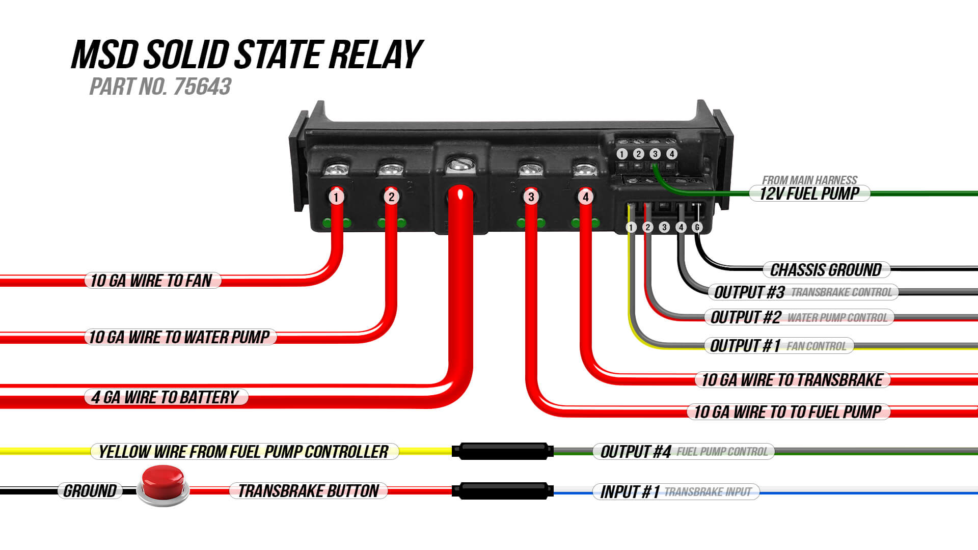
The wiring of the Digital 6AL is routed out one end of the unit through a sealed and locking connector. Clean up your wiring with an MSD Solid State Relay Block. Transbrake Wiring Diagram - thank you for visiting our site.
MSD Power Grid Installation Diagram Eliminates the 7AL or 6AL Box. MSD is pleased to announce that this transmission controller was designed with performance. MSD Atomic Transmission Control Module Stand-alone TCM PN 2760.
Figure 13 MSD 2760 Atomic Transmission Controller Diagnostics Summary M S D W W W. Not only will the engine benefit from MSDs full power CD sparks but there is also an adjustable boosttiming retard circuit to prevent detonationWhen your turbo or blower forces the airfuel mixture into the engine the cylinder pressure inside the combustion chamber increases. MSD Atomic Transmission Control Module PN 2760 Thank you for purchasing the MSD Atomic Transmission Control Module TCM.
I got a MSD 7AL 3 box its just a 2 wires coming out of the. 4 independent channels can be activated using either power or ground. Wiring Diagrams Msd Ignition System 6al Coil 6a At Diagram.
The Hot Rod Garage Wiring Information with regard to Transbrake Wiring Diagram image size 726 X 521 px and to view image details please click the image. With 4 channels providing up to 200 Amps of momentary or 80 Amps constant combined power. Hipsters Transbrake Solenoids whether for Turbo PN.
Conversions Hybrids - MSD user need some help please it has the wiring diagram and color coding and tells where each wire goesJun 03 Re. This module takes the place of 4 standard relays and eliminates unsightly wiring. Today we are pleased to announce that we have discovered a very interesting topic to be reviewed Description.
Trans brake wiring and placement Hipsters Transbrake Solenoid Wiring Diagram. The different rpm modules are activated when 12 volts are applied to a corresponding wire. For installation of the brackets and trigger.
The MSD 6AL Ignition Control set the standards that other ignitions strive to reach. This helps keep tire temperatures consistent. The line of MSD 6-Series Ignitions are the most popular aftermarket ignitions in the world due to our race-proven.
Or Powerglide PN.
 Msd 8460 Wiring Diagram Diagram Wire Automotive Electrical
 Basic Hot Rod Engine Hei Wiring Diagram And Sbc Engine Ignition Wiring Catalogue Of Schemas Diagram Engineering Rod
Msd 2 Step Wiring Diagram Passport Fuse Box Diagram Hinoengine Losdol2 Jeanjaures37 Fr
 Wiring Diagram Msd Solid State Relay 1985 Ford Mustang Holley My Garage
 18 Msd Wiring Diagram Sprint Car Diagram Electrical Diagram Wire


